OSPF Configuration 2
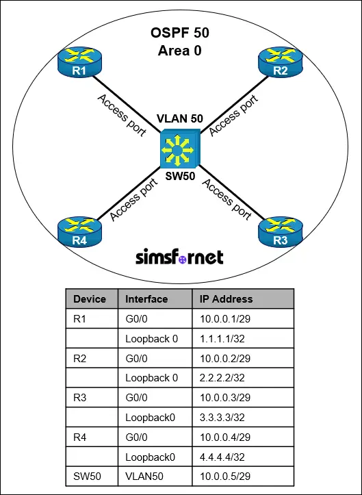
Topology

Tasks:
IP connectivity has been established. OSPF must be configured using process-id 50 in the order presented to complete the implementation. No static or other dynamic routing protocols are included.
- Configure OSPF Area 0 with process ID 50 on all devices under their respective interfaces connected to VLAN 50. Do not use the network command under the OSPF process.
- Using a host wildcard mask, configure all the routers to advertise their respective Loopback0 networks.
- Configure R1 to always be the DR with max possible value.
- SW50 should be configured not to participate in the DR/BDR election.
Solution:
Task 1:
Configure OSPF Area 0 with process ID 50 on all devices under their respective
interfaces connected to VLAN 50. Do not use the network command under the OSPF
process.
Instead of the network command, ip ospf area command can be
used under each interface. For the SW50, we need to enable OSPF on its VLAN 50
interface.
On R1:
R1#configure terminal
R1(config)#interface g0/0
R1(config-if)#ip ospf 50 area 0
On R2:
R2#configure terminal
R2(config)#interface g0/0
R2(config-if)#ip ospf 50 area 0
On R3:
R3#configure terminal
R3(config)#interface g0/0
R3(config-if)#ip ospf 50 area 0
On R4:
R4#configure terminal
R4(config)#interface g0/0
R4(config-if)#ip ospf 50 area 0
On SW50:
SW50#configure terminal
SW50(config)#interface vlan50
SW50(config-if)#ip ospf 50 area 0
ip ospf 50 area 0 command allows the interfaces to participate in
OSPF area 0 by sending and receiving OSPF Hello packets to form neighbor
relationships and advertise the directly connected network. In this command,
"50" is the process-id which is required.
Task 2: Using a
host wildcard mask, configure all the routers to advertise their respective
Loopback0 networks.
A host wild
card is 0.0.0.0 which is equivalent to subnet mask 255.255.255.255 (/32), which
means a single address. For this task, we need to use the network command under
the OSPF process.
On R1:
R1(config-if)#router ospf 50
R1(config-router)#network 1.1.1.1 0.0.0.0 area 0
On R2:
R2(config-if)#router ospf 50
R2(config-router)#network 2.2.2.2 0.0.0.0 area 0
On R3:
R3(config-if)#router ospf 50
R3(config-router)#network 3.3.3.3 0.0.0.0 area 0
On R4:
R4(config-if)#router ospf 50
R4(config-router)#network 4.4.4.4 0.0.0.0 area 0
This command
advertises the exact IP address of the Loopback0 interfaces by specifying a
host wildcard mask (0.0.0.0), associating it with Area 0.
Task 3:
Configure R1 to always be the DR with max possible value.
On OSPF
broadcast networks, the Designated Router (DR) is elected based on OSPF
priority. The device with higher priority is elected as the DR. The default
OSPF priority is 1 while the maximum is 255. By setting the maximum OSPF
priority (255), R1 will always win the DR election.
On R1:
R1(config-router)#interface g0/0
R1(config-if)#ip ospf priority 255.
No
configuration changes are needed on the other devices because the default OSPF
priority is 1. This means that
they cannot compete with R1 for the DR role.
Task 4: SW50
should be configured not to participate in the DR/BDR election.
A device with 0
priority doesn't participate in DR/BDR elections.
On SW50:
SW50(config-if)#ip ospf 50 area 0
Verification:
Reset the OSPF
process on the devices for configurations to take effect.
R1(config-if)end
R1#clear ip ospf process
R1#Reset ALL OSPF processes? [no]: yes
R2(config-router)end
R2#clear ip ospf process
R2#Reset ALL OSPF processes? [no]: yes
R3(config-router)end
R3#clear ip ospf process
R3#Reset ALL OSPF processes? [no]: yes
R4(config-router)end
R4#clear ip ospf process
R4#Reset ALL OSPF processes? [no]: yes
SW50(config-if)end
SW50#clear ip ospf process
SW50#Reset ALL OSPF processes? [no]: yes
Now check if R1
is the DR by using show
ip ospf neighbor command on any of the devices.
R2#show ip ospf neighbor
Neighbor
ID Pri State Dead Time Address Interface
1.1.1.1 255
FULL/DR 00:00:32 10.0.0.1 GigabitEthernet0/0
10.0.0.5 0
2WAY/DROTHER 00:00:37 10.0.0.5 GigabitEthernet0/0
4.4.4.4 1
FULL/BDR 00:00:36 10.0.0.4 GigabitEthernet0/0
3.3.3.3 1
2WAY/DROTHER 00:00:32 10.0.0.3 GigabitEthernet0/0
Full/DR means
that R1 is the DR. SW50 has priority of 0 so it is neither DR nor BDR and
doesn't participate in the election. Routers in the network form full
adjacencies (reach the FULL state) only with the DR and BDR. Non-DR/BDR routers
form a 2WAY state with each other to conserve resources and avoid redundant
link-state updates. That is why R2 is in a 2WAY state with the other DROTHERs
Now save the
configuration.
R1#write memory
R2#write memory
R3#write memory
R4#write memory
SW50#write memory
Packet Tracer File
Clicking this button will begin the download of a ZIP file. Inside the ZIP file, you'll find a Packet Tracer Activity (.pka) file, which will automatically track your progress as you configure the network.


