Voice VLAN Configuration 1
Topology
Tasks:
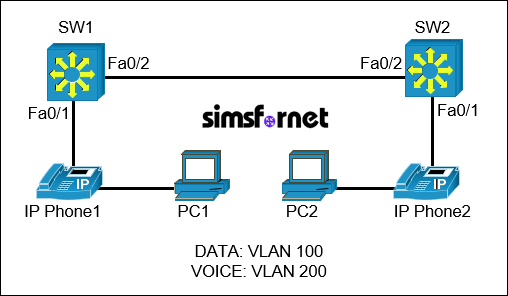
A company is setting up a new network and requires separate VLANs for data and voice traffic. This ensures that voice traffic is prioritized, providing better call quality for IP phones. There are two switches, SW1 and SW2, connected to each other. Each switch has one port connected to an IP phone and a PC. The IP phone is configured to pass data to the PC.
- Create VLANs for Data and Voice Traffic
- Configure VLAN 100 for data traffic, named "DATA".
- Configure VLAN 200 for voice traffic, named "VOICE".
- Configure Access Ports for IP Phone and PC Connectivity
- Configure the ports connected to the IP phones to support both data and voice VLANs, allowing the PCs to connect through the IP phone.
- Set Up Inter-Switch Link
- Configure the link between SW1 and SW2 to allow traffic for both VLANs.
Solution:
Task 1: Create
VLANs for Data and Voice Traffic
- Configure VLAN 100 for data
traffic, named "DATA".
- Configure VLAN 200 for voice
traffic, named "VOICE".
We will create two
VLANs on both switches. VLAN 100 named "DATA" for data traffic and
VLAN 200 named "VOICE" for voice traffic. This will ensure that both
VLANs are recognized on both switches.
On SW1:
SW1#configure
terminal
SW1(config)#vlan 100
SW1(config-vlan)#name DATA
SW1(config-vlan)#vlan 200
SW1(config-vlan)#name VOICE
SW1(config-vlan)#exit
On SW2:
SW2#configure
terminal
SW2(config)#vlan 100
SW2(config-vlan)#name DATA
SW2(config-vlan)#vlan 200
SW2(config-vlan)#name VOICE
SW2(config-vlan)#exit
Task 2: Configure
Access Ports with Data and Voice VLANs
We need to set
FastEthernet0/1 as an access port on both switches and assign VLAN 100 as the
data VLAN and VLAN 200 for voice traffic. This allows the IP phone to tag its
own voice traffic with VLAN 200, while untagged traffic (from the PC) defaults
to VLAN 100.
On SW1:
SW1(config)#interface
f0/1
SW1(config-if)#switchport mode access
SW1(config-if)#switchport access vlan 100
SW1(config-if)#switchport voice vlan 200
On SW2:
SW2(config)#interface
f0/1
SW2(config-if)#switchport mode access
SW2(config-if)#switchport access vlan 100
SW2(config-if)#switchport voice vlan 200
Task 3: Set Up
Inter-Switch Link
- Configure the link between SW1
and SW2 to allow traffic for both VLANs.
We need to configure
the link between SW1 and SW2 as a trunk link and allow it to carry both VLAN
100 (Data) and VLAN 200 (Voice).
On SW1:
SW1(config-if)#interface
f0/2
SW1(config-if)#switchport trunk encapsulation dot1q
SW1(config-if)#switchport mode trunk
SW1(config-if)#switchport trunk allowed vlan 100,200
On SW2:
SW2(config-if)#interface
f0/2
SW2(config-if)#switchport trunk encapsulation dot1q
SW2(config-if)#switchport mode trunk
SW2(config-if)#switchport trunk allowed vlan 100,200
Now exit the
configuration mode and save the configuration.
SW1(config-if)#end
SW1#write memory
SW2(config-if)#end
SW2#write memory
Verification:
Verify VLAN and
Trunk configurations using:
SW1#show vlan brief
SW1#show interfaces trunk
Packet Tracer File
Clicking this button will begin the download of a ZIP file. Inside the ZIP file, you'll find a Packet Tracer Activity (.pka) file, which will automatically track your progress as you configure the network.