
LACP configuration 1
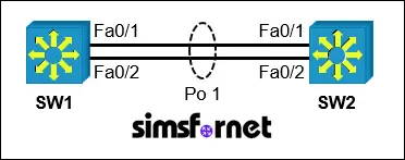
Topology
Tasks:
A company requires a high-availability link between two switches (SW1 and SW2) to provide redundancy and increased bandwidth. LACP (Link Aggregation Control Protocol) is to be used to create an EtherChannel between the switches.
- Configure an LACP EtherChannel with the number 1 between SW1 and SW2 using FastEthernet0/1 and FastEthernet0/2 on both switches. The LACP mode must match on both ends.
- Set the EtherChannel to operate as a trunk link using IEEE 802.1Q tagging.
- Assign VLAN "Control" as the native VLAN for the trunk link.
Solution:
Task 1: Configure an
LACP EtherChannel with the number 1 between SW1 and SW2 using FastEthernet0/1
and FastEthernet0/2 on both switches. The LACP mode must match on both ends.
LACP uses two modes,
'active' and 'passive' mode. In active mode, a switch actively
initiates and negotiates the formation of an EtherChannel by sending LACP
packets to its counterpart. In passive mode, a switch listens for
LACP packets but does not actively initiate the negotiation. At least one end
of the link must be configured in active mode for LACP to form
an EtherChannel.
Active + Passive or Active + Active combinations
will successfully form an EtherChannel. As the LACP mode must match on both
ends, Both the switches must be configured in active mode. If both
devices are in passive mode, EtherChannel will not form
because neither initiates the negotiation.
On SW1:
SW1#configure
terminal
SW1(config)#interface range f0/1-2
SW1(config-if-range)#channel-group 1 mode active
SW1(config-if-range)#exit
On SW2:
SW2#configure
terminal
SW2(config)#interface range f0/1-2
SW2(config-if-range)#channel-group 1 mode active
SW2(config-if-range)#exit
The interface range command allows us to configure the interfaces
collectively which can save a lot of time. channel-group 1 mode active enables LACP in active mode on
interfaces FastEthernet0/1 and FastEthernet0/2 and assigns them to EtherChannel
group 1.
Task 2: Set the
EtherChannel to operate as a trunk link using IEEE 802.1Q tagging.
To configure the
etherchannel we created, we need to use the interface port-channel 1 command. Remember that
etherchannel in Cisco IOS is sometimes also called channel-group and
port-channel.
On SW1:
SW1(config)#interface
port-channel 1
SW1(config-if)#switchport trunk encapsulation dot1q
SW1(config-if)#switchport mode trunk
SW1(config-if)#end
On SW2:
SW2(config)#interface
port-channel 1
SW2(config-if)#switchport trunk encapsulation dot1q
SW2(config-if)#switchport mode trunk
SW2(config-if)#end
switchport trunk
encapsulation dot1q specifies the use of IEEE 802.1Q for VLAN tagging. switchport mode trunk configures the EtherChannel as a
trunk link.
Task 3: Assign VLAN
"Control" as the native VLAN for the trunk link.
First use the show
vlan brief command on both switches to find out the
"Control" VLAN.
On SW1:
SW1#show vlan brief
VLAN Name Status Ports
---- --------------------------------
--------- -------------------------------
--output omitted--
99
Control
active
On SW2:
SW2#show vlan brief
VLAN Name Status Ports
---- --------------------------------
--------- -------------------------------
--output omitted--
99
Control
active
The output shows
that "Control" VLAN is VLAN 99.
On SW1:
SW1#configure
terminal
SW1(config)#interface port-channel 1
SW1(config-if)#switchport trunk native vlan 99
SW1(config-if)#end
On SW2:
SW2#configure
terminal
SW2(config)#interface port-channel 1
SW2(config-if)#switchport trunk native vlan 99
SW2(config-if)#end
Verifcation:
Use the show etherchannel summary command on both switches to
verify.
On SW1:
SW1#show
etherchannel summary
--output omitted--
Group
Port-channel Protocol Ports
------+-------------+-----------+----------------------------------------------
1
Po1(SU) LACP Fa0/1(P) Fa0/2(P)
On SW2:
SW1#show
etherchannel summary
--output omitted--
Group
Port-channel Protocol Ports
------+-------------+-----------+----------------------------------------------
1
Po1(SU) LACP Fa0/1(P) Fa0/2(P)
"SU" means
that etherchannel formation was successful.
Now save the
configuration.
SW1#write memory
SW2#write memory
Packet Tracer File
Clicking this button will begin the download of a ZIP file. Inside the ZIP file, you'll find a Packet Tracer Activity (.pka) file, which will automatically track your progress as you configure the network.